Anybody that ever did some programming on a Unix based system will be familiar with Core Dumps, but ever wondered where that name came from?
It comes from a time (1950s - 1970s) where computer stored data on ferrite cores, a lot of tiny ferrite cores. And in case something went wrong, the data stored on those tiny ferrite cores was printed, dumped, on paper to be analyzed, a core dump.

The above module was part of a Soviet era Saratov-2 computer, that was comparable to the PDP-8.
Writing Bits
Without data there is nothing to be dumped, so how is that data stored on those ferrite cores? First of all, every one of those ferrite cores only stores a single bit of data. This bit (0 or 1) is represented by the direction of residual magnetic field in the ferrite core (the red arrows in the image below).
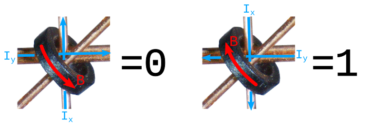
The next question is of course how can those ferrite cores be magnetized, that’s where the wires, that are woven through the cores, come into play. When an electric current flows trough those wires they act as tiny electro magnets, and the magnetic field will depend on the strength and direction of that electric current. The direction of the magnetic field in relation to the electric current can be determined via Ampère’s right-hand grip rule.
In the image above the blue arrow is the electric current and the red arrow the resulting magnetic field (for simplicity I picked a random wire, what all 4 wires are use for is explained below). The ferrite cores need a certain amount of current to saturate and stay magnetized after the current is removed. Due to the hysteresis it takes that same amount of electric current in the other direction to switch the magnetic field. The electric current that is needed to saturate the ferrite core is called Is.
So by changing the direction of the electric current a 0 or a 1 can be written, but writing every bit to 0 or 1 at the same time isn’t very useful.
Addressing Bits
Since the module consists of 4096 cores some way of addressing those 4096 bits is needed. The module is organized in a 64 by 64 matrix. From the 4 wires through every core there are 2 address lines called X and Y.
By reducing the electric current through the X and Y wires to 50% of Is it means that if there only flows current through the X or the Y wire it is not enough to magnetize the core. So to write a bit there must flow electric current through both the X and Y wires.
When there flows electric current through both X and Y there are 4 combinations, when both currents flow in the same direction through the core the combined magnetic field will be enough to magnetize the cores.
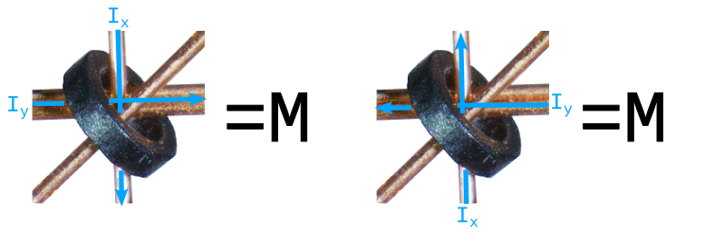
When both currents flow in the opposite direction the magnetic field cancel each other out, and the direction of the field in the core will stay unchanged.
So by having one X and one Y wire that conduct current we can selectively write any of the 4096 bits of this module. But a write-only-memory is not very useful, we also want to read back the data.
Reading Bits
For reading the 3rd wire, the sense wire, is needed. When the magnetic field of a core “switches” direction a small electric pulse will be generated on the sense wire (and all other wires for that mather). To trigger this, a 0 is written to the bit, if it was 0 the magnetic field wil not switch and no pulse wil be generated, when the bit was 1 the field changes and a pulse is generated. When a 1 was read it will have to be re-written to the core because that now holds a 0.
The 4th Wire
The 4th wire is the inhibit wire, to understand what this does it is needed to understand that the module shown is only one bit-plane, to created a word of multiple bits several of these modules are combined in a stack. The X and Y address lines are serialized to reduce control logic. This means that when writing a bit the same bit in all planes would be written.
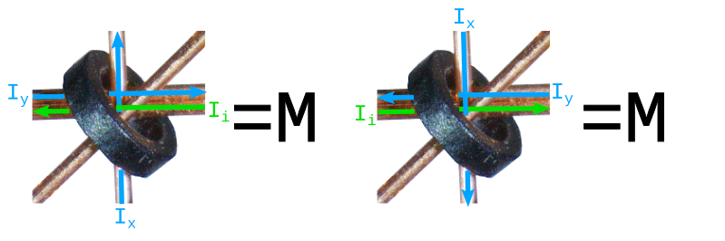
To prevent this every bit plane has an inhibit line, that has a current flow (the green arrow in the image above) in the opposite direction of the Y line and that way cancels out the magnetic field of that bit plane. That way only the bit plane that has the inhibit line deactivated will be written.
For reading it is not needed to inhibit bit planes, but as explained earlier, reading also means writing back the destroyed data.
Next Steps
In the next part we will determine the Is current of the module and build up the circuit needed to write and read a bit. The circuit needed will consist of a current source that can switch direction and an opamp based sense amplifier.
Feedback
Feel free to give feedback on Linkedin