One of my first projects when I started working for transtechnik (now ETC) was a DMX512 router, called E-Gate. References to that project can still be found on the ETC website. And even the windows software I wrote, called E-Gatekeeper, can still be downloaded, and it still works (even on Windows 10)

(E-gatekeeper screenshot image copyright by ETC GmbH)
The hardware was based on a Motorola (now NXP) PowerPC MPC860 CPU with a Xilinx FPGA. Back then (this was early 2000) the FPGA design was not done by me, but FPGA’s always fascinated me.
Now with FPGA’s like the Xilinx Zynq, connecting the FPGA to a CPU became very easy and designing something like a DMX512 router where the CPU receives for example Art-Net and the FPGA transmits DMX512 has become a lot easier.
With Vivado connecting the ARM cpu with the FPGA can be done via an AXI interface. In my design I used one AXI interface to connect the ARM CPU to a dual port BRAM of 4 Kbyte, and an AXI-lite one to let the ARM cpu program the config registers on the DMX module.
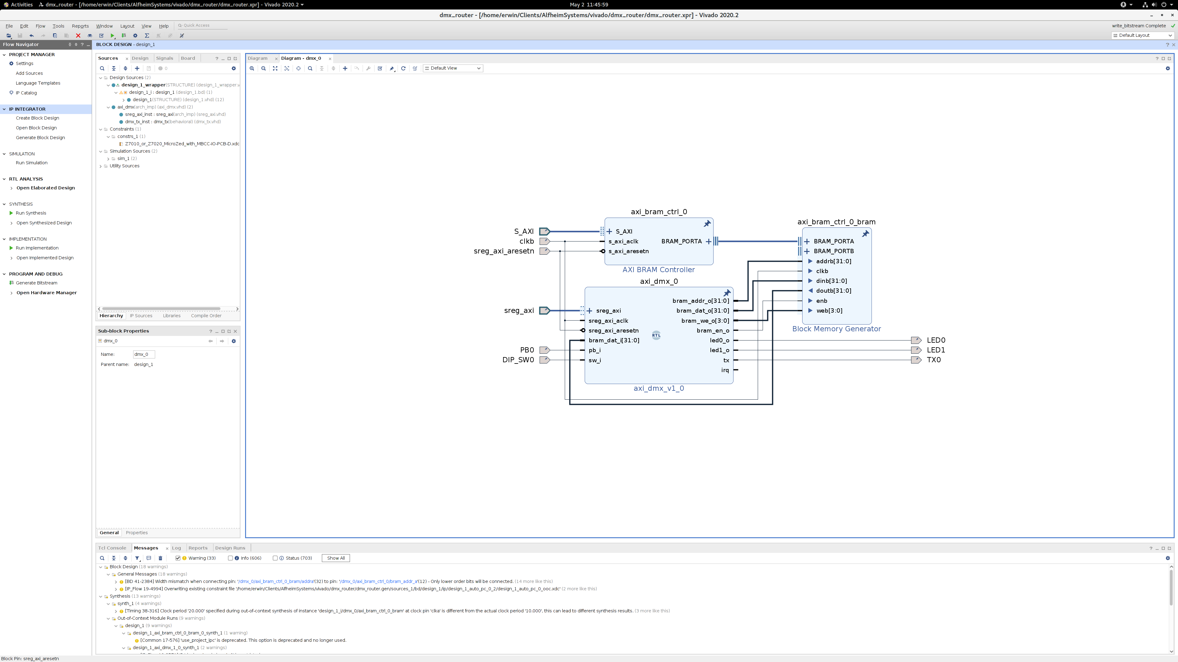
To connect four of those DMX modules to the ARM CPU two AXI interconnects are used.

From the software side the two AXI busses show up as a memory region that can be read and written. The results of the memory access is a read or write to the FPGA module (in this case read/write the the BRAM or to the DMX module registers). The easy, and very insecure, way to access the AXI busses under Linux is to simply mmap /dev/mem.
note: this can not be done with tools like dd or hexdump, because they try to lseek on /dev/mem and that is not supported, so a small C program is needed.
static volatile uint8_t* mem_ptr;

int fd = open("/dev/mem", O_RDWR);
if (fd == -1) {
  return -1;
}

mem_ptr = (volatile uint8_t*)mmap(NULL, MEM_SIZE, PROT_READ|PROT_WRITE, MAP_SHARED, fd, (off_t)MEM_OFFSET);
if (mem_ptr == MAP_FAILED) {
  return -1;
}
The MEM_SIZE and MEM_OFFSET are in this case 0x40000000 and 4096, which can be setup in the Vivado address editor. After mmap’ing the memory pointer can be used like normal memory
for(uint32_t i=0; i < MEM_SIZE;++i) {
  mem_ptr[i] = 0;
}
In this design the second AXI bus is used for the DMX module registers, but the concept is exactly the same, mmap the address and simply write to that address;
write_reg( REG_NR_START_CODE_1, 0x00);
write_reg( REG_NR_MBB_TIME_1, (100 * 8));
write_reg( REG_NR_BREAK_TIME_2, (100 * 180));
write_reg( REG_NR_MEM_PTR_1, 0x00);
write_reg( REG_NR_FRAME_LEN_1, 513);
This code example sets the DMX start code to 0x00 (normal DMX channel data), the Mark Before Break time to 800 (in units of 10ns so 800 is 8us), the Break time to 180us, the start offset of the DMX data to 0 (relative to the BRAM address) and the frame length to 513 bytes (512 data bytes that are read from BRAM, and the start code byte).
The write_reg() function simply write to the mapped address
static volatile uint32_t* reg_ptr;

static void write_reg(uint32_t offset, uint32_t value)
{
  if (offset >= REG_SIZE) {
    return;
  }

  reg_ptr[offset] = value;
}
The VHDL side for a DMX output is not even that complicated, it is basically a FSM that goes through states like break, startbit, databits, etc.
--
-- TX FSM
--
v.bit_counter := reg.bit_counter - 1;

case reg.state is

  when st_idle =>
    v.tx_o := '1';
    if (unsigned(reg.current_desc.frame_len) /= 0) then
      v.bit_counter := reg.current_desc.mbb_time;
      v.state := st_mbb;
    end if;

  when st_mbb =>
    if (reg.bit_counter = 0) then
      v.tx_o        := '0';
      v.bit_counter := reg.current_desc.break_time;
      v.state       := st_break;
    end if;

  when st_break =>
    if (reg.bit_counter = 0) then
      v.tx_o        := '1';
      v.bit_counter := reg.current_desc.mab_time;
      v.state       := st_mab;
    end if;

  when st_mab =>
    if (reg.bit_counter = 0) then
      v.tx_o          := '0';
      v.bit_counter   := BIT_TIME;
      v.state         := st_start_bit;
      v.current_byte  := reg.current_desc.start_code;
      v.byte_counter  := (others => '0');
    end if;

  when st_start_bit =>
    if (reg.bit_counter = 0) then
      v.bram_addr_o             := std_logic_vector(unsigned(reg.current_desc.mem_ptr) +  reg.byte_counter);
      v.tx_o                    := reg.current_byte(0);
      v.bit_counter             := BIT_TIME;
      v.state                   := st_data_bit_0;
    end if;

  when st_data_bit_0 =>
    if (reg.bit_counter = 0) then
      v.tx_o          := reg.current_byte(1);
      v.bit_counter   := BIT_TIME;
      v.state         := st_data_bit_1;
    end if;

  when st_data_bit_1 =>
    if (reg.bit_counter = 0) then
      v.bit_counter   := BIT_TIME;
      v.tx_o          := reg.current_byte(2);
      v.state         := st_data_bit_2;
    end if;

  when st_data_bit_2 =>
    if (reg.bit_counter = 0) then
      v.bit_counter   := BIT_TIME;
      v.tx_o          := reg.current_byte(3);
      v.state         := st_data_bit_3;
    end if;

  when st_data_bit_3 =>
    if (reg.bit_counter = 0) then
      v.bit_counter   := BIT_TIME;
      v.tx_o          := reg.current_byte(4);
      v.state         := st_data_bit_4;
    end if;

  when st_data_bit_4 =>
    if (reg.bit_counter = 0) then
      v.bit_counter   := BIT_TIME;
      v.tx_o          := reg.current_byte(5);
      v.state         := st_data_bit_5;
    end if;

  when st_data_bit_5 =>
    if (reg.bit_counter = 0) then
      v.bit_counter   := BIT_TIME;
      v.tx_o          := reg.current_byte(6);
      v.state         := st_data_bit_6;
    end if;

  when st_data_bit_6 =>
    if (reg.bit_counter = 0) then
      v.bit_counter   := BIT_TIME;
      v.tx_o          := reg.current_byte(7);
      v.state         := st_data_bit_7;
    end if;

  when st_data_bit_7 =>
    if (reg.bit_counter = 0) then
      v.bit_counter   := BIT_TIME;
      v.tx_o          := '1';
      v.state         := st_stop_bit_0;
    end if;

  when st_stop_bit_0 =>
    case reg.bram_addr_o(1 downto 0) is
        when "00" => v.current_byte := bram_dat_i( 7 downto  0);
        when "01" => v.current_byte := bram_dat_i(15 downto  8);
        when "10" => v.current_byte := bram_dat_i(23 downto 16);
        when "11" => v.current_byte := bram_dat_i(31 downto 24);
        when others => null;
    end case;
    if (reg.bit_counter = 0) then
      v.byte_counter  := reg.byte_counter + 1;
      v.bit_counter   := BIT_TIME;
      v.tx_o          := '1';
      v.state         := st_stop_bit_1;
    end if;

  when st_stop_bit_1 =>
    if (reg.bit_counter = 0) then
      if (reg.byte_counter = unsigned(reg.current_desc.frame_len)) then
        v.tx_o          := '1';

        if (unsigned(reg.next_desc.frame_len) /= 0) then
            -- get the next frame
          v.current_desc  := reg.next_desc;
          v.next_desc     := reset_desc;
          v.state         := st_mbb;
          v.bit_counter   := reg.next_desc.mbb_time;
        else
          v.current_desc  := reset_desc;
          v.state         := st_idle;
          --v.bit_counter   := reg.current_desc.mbb_time;
        end if;
      else
        if (reg.current_desc.mad_time = 0) then
          v.tx_o        := '0';
          v.bit_counter := BIT_TIME;
          v.state       := st_start_bit;
        else
          v.tx_o        := '0';
          v.bit_counter := reg.current_desc.mad_time;
          v.state       := st_mad;
        end if;
      end if;
    end if;

  when st_mad =>
    if (reg.bit_counter = 0) then
      v.tx_o            := '0';
      v.bit_counter     := BIT_TIME;
      v.state           := st_start_bit;
    end if;

  when others =>
    v.state := st_idle;

end case;
The complete code is of course a bit more complex, and can be found here ; dmx_tx.vhd and axi_dmx.vhd.
I didn’t make the complete project available because it is still in flux, I for example still want to add DMX input support.
Compared to a CPU+UART combination a CPU+FPGA combination has way better timing control. For example this design allows to set break time with 10ns steps and the FPGA always generates the break with exactly the configured time, and has almost no jitter.

Especially short times that are smaller than 1ms are hard to do consistently with a CPU-only solution, especially when the CPU has more to do like running a full Linux OS (Xilinx PetaLinux in this case). A FPGA solution has no problem consistently generating timing pulses of 10ns, or in this application the 4us wide bit times needed for the 250kbit/s DMX512 signal.
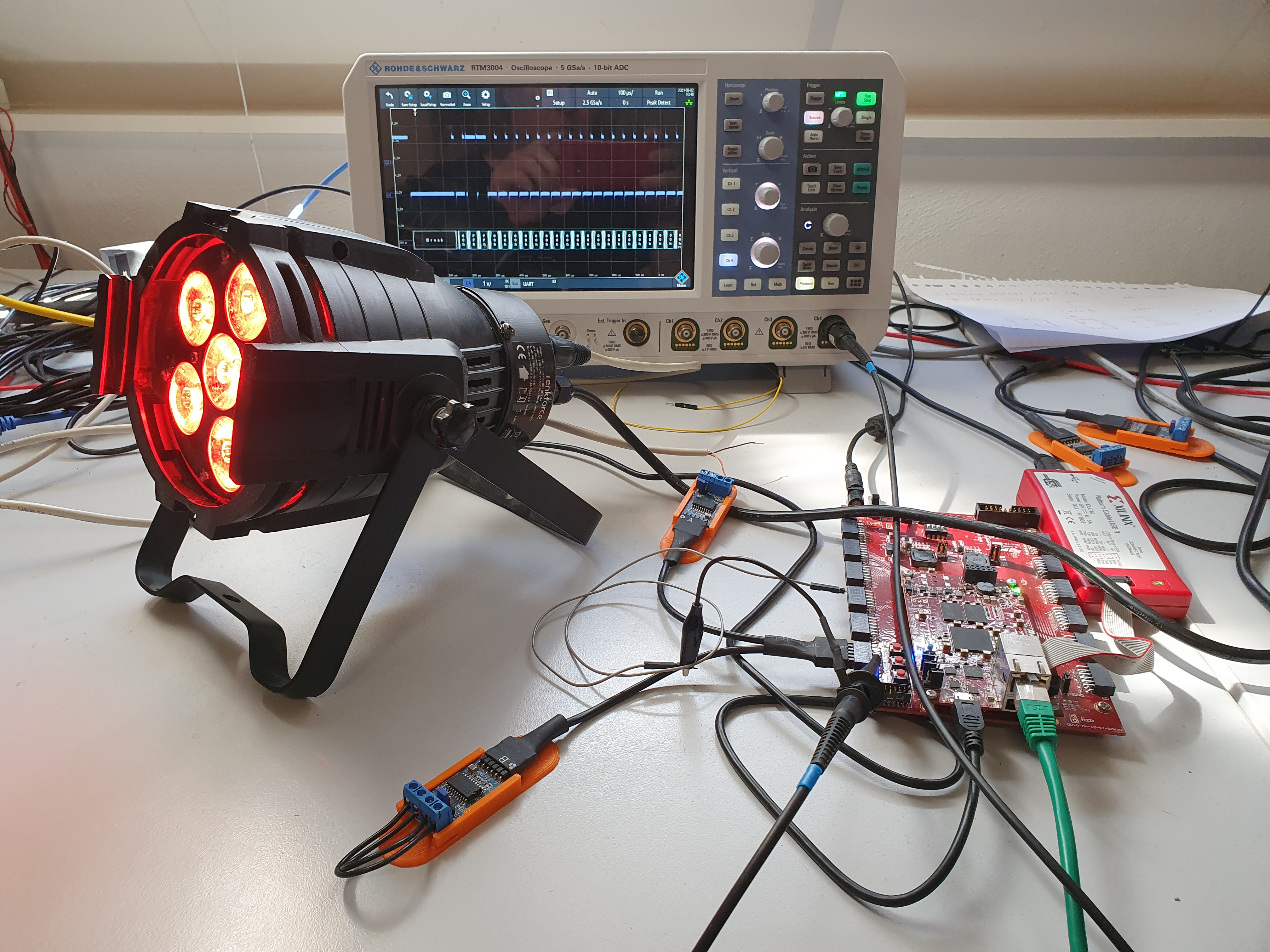
Of course looking at a signal on a scope is a nice way to check if it is looking as expected, but it the end it has to work in the real world. In this test I used a Microzed with a baseboard and a Digilent PmodRS485. As DMX test device I used an el-cheapo Renkforce LED par can.
Even though already mentioned, the use of /dev/mem to access hardware is in real world applications an absolute no-go, because it means the application needs root rights and can access the complete kernel memory space, which is an unacceptable security risk. Also the default PetaLinux setup with a writable VFAT file system is really not suitable for real products because it will destroy the SD-card in no time, and offers no safety against unclean system shutdowns, which will always happen when the user simply unplugs the device.
Feedback
Feel free to give feedback on Linkedin