The MOS Technology 6581/8580 SID (Sound Interface Device) is the almost 40 year old sound chip that was used in the famous Commodore 64. It uses a 5bit address / 8bit data synchronous bus with a chip select, rw, and clock signal. Since the chip uses the 1MHz (well not exactly 1MHz as I’ll explain later) clock signal also to generate all the audio frequencies, so it is important that the clock signal is stable, even though the read/write access would work fine with a unstable clock as long as the signal setup times are correct.
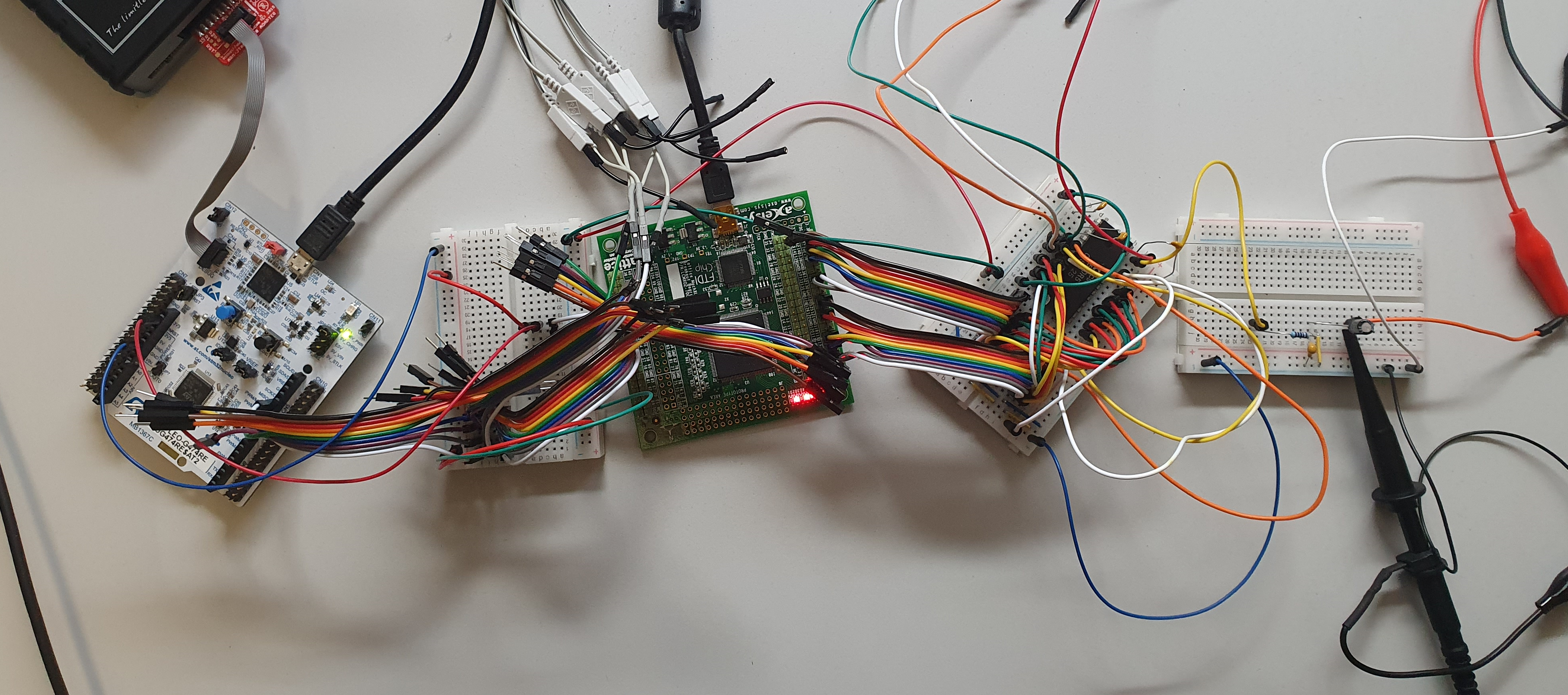
Since it would need 5 address + 8 data + clk + cs + rw + rst = 17 pins to connect it to a microcontroller I decided it would be easier to use a FPGA and make a SPI to SID bridge. That way any microcontroller that has a SPI bus can access the SID chip. The picture above shows, from left to right, a STM32G4 board running Zephyr, a bread board used to tap the signals with the logic analyzer, a Lattice MachXO2 board, and the bread board with the SID chip.
VHDL
Since I am not exactly a VHDL guru, getting the FPGA to work was rather tricky, and I am sure people that write VHDL for their daily will look at it and think what the hell did he do there, but it seems to work. The main problem was that there are two clock domains, the SPI clock and the SID clock, and those two clocks are completely independent. To create one clock domain I decided to synchronize the SPI clock with the SID clock with a dual flip-flop setup. This however means the SID clock needs to be faster than the SPI clock. The SPI clock can be about 20MHz, so the SID clock needs to be at least 100MHz. But the SID also needs that 1MHz signal. As mentioned before, that 1MHz isn’t exactly 1MHz, depending on if it was a PAL or NTSC C64, the SID clock was a bit less or a bit more than 1MHz. This is because the clock is generated from the clock that is needed to generate the 50Hz PAL or the 60Hz NTSC video signal (here is a good description on the C64 clocks)
For the PAL version the C64 has a 17.734472MHz clock, this is than divided by 18 to get the ~985kHz SID clock. The MachXO2 has an internal oscillator that can generate a 17.73MHz clock, this is close enough to the needed PAL-C64 clock. The MachXO2 also has a PLL that can be used to multiply that 17.73MHz clock to 106.4Mhz what is fast enough to sample the 20MHz SPI clock.
SPI
The SID needs an 5bit address and 8bit data, those bits are packed in two bytes that are send to the FPGA via the SPI-bus. The first byte is split into 2 parts, a 2 bit command and 6 address bits. There is one extra address bit, to allow a second SID in the future. The 4 command bit combinations are;
00reset SID, when this command is send the address and data bits are ignored, and the SID is reset.01read SID register, when this command is send the address bits select the SID register to read, the data bits are ignored. Since the SID read cycle can only start after the SPI command is complete the read result is send on the MISO line with the next SPI transfer. Until a new read command is send the same (probably stale) register data will be send on the MISO line.10write SID register, when this command is send the 8 data bits will be written to the selected SID register.11reserved for future use.
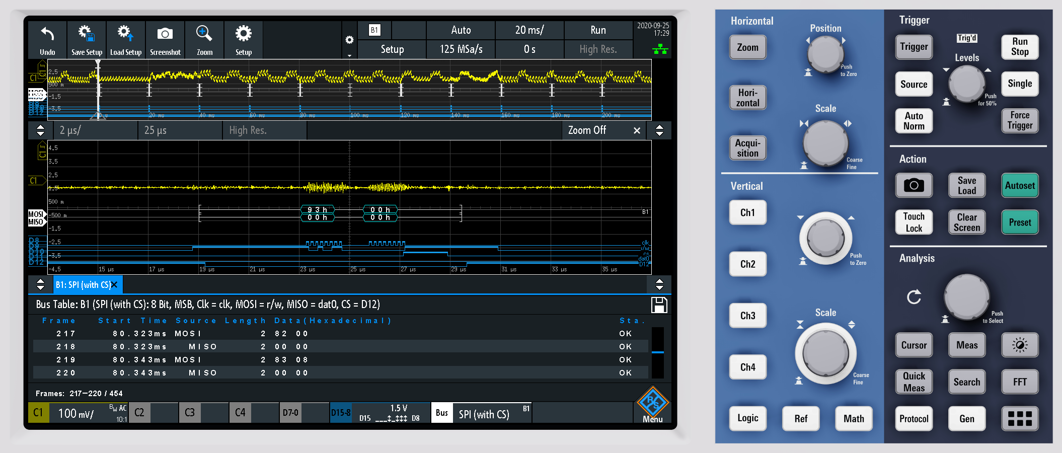
On the scope are several SPI transfers visible, for example 0x82 0x00 which write 0x00 to SID register 2 (PW LO), and 0x83 0x08 which writes 0x08 to SID register 3 (PW HI), together they they set the pulse width to 0x0800 what results in a pulse width of 0x0800 / 40.95 = 50.01%
What the scope also shows is that the SPI commands come in burst with a 20ms interval, and that brings us to the SID player software.
SID player
The C64 SID files are basically just MOS6510 machine code programs that are executed on the C64, that means to play SID files some sort of C64 emulator is needed.
Different from SID players like VLC there is no need to actually generate sound samples, because that is what the SID chip is for. Instead of generating the sound samples the SID player sends the commands via the SPI bus and the FPGA to the SID chip.
A SID file basically has 3 parts, a header with some info, a piece of machine code that initializes the hardware, and a piece of machine code that is executed from a timer IRQ handler. And the 20ms cycle, seen on the scope, is the 50Hz timer IRQ cycle. Currently this is fixed to 50Hz in software, but it could be generated by the FPGA to have a more exact timing. But since this is just a little weekend project it is unlikely I’ll make those extensions.
Since to play SID files a C64 emulator is needed, a CPU with enough RAM (the C64 needs 64 kbyte) must be used, I picked the STM32G474 on a Nucleo board that is supported by Zephyr. To keep things simple the SID file is compiled into the program, they are only a few kbyte in size anyway. Since everything is available on GitHub feel free to take a look how things work.
And now the result, Big Fun Tune 5 by fellow Dutchman Edwin van Santen
Getting the Source Code
The source code of the SID player spi_sid and the FPGA spi_sid_fpga are hosted on GitHub. You can use the following git commands to clone the sources
git clone git://github.com/lowlander/spi_sid.git
and
git clone git://github.com/lowlander/spi_sid_fpga.git
Feedback
Feel free to give feedback on Linkedin